- Arduino UNO
-
- Arduino Leonardo
-
- Arduino NANO
-
- Arduino Pro mini
-
- Arduino Pro micro
-
- ESP8266 GPIO
-
- NodeMCU 1.0 (ESP8266)
-
- WeMos D1 mini (ESP8266)
-
- NodeOLED (ESP8266)
-
- ESP-01 (ESP8266)
-
- ESP32 DevBoard (ESP32)
-
- Node ESP-32S (ESP32)
-
- Ai-Thinker ESP12K (ESP32-S2)
-
- Mediatek Linkit 7697 Nano
-
- Mediatek Linkit 7697 Nano Board
-
- Mediatek Linkit 7697 Bit
-
- Microbit
-

2022年2月13日 星期日
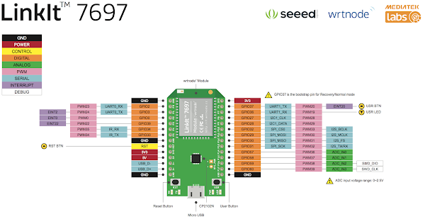
常用微控制板接腳圖 (Pin Layout)




2022年2月4日 星期五
讓 U8G2 OLED 函式庫在 Arduino 中活用
快速連結
- u8g2 建構子 (Constrator)
- u8g2 在各類顯示器上的測試結果
- u8g2 函式庫載點 (GitHub)
- u8g2 支援字型列表
- u8g2 基本函式庫
- u8g2 繪圖函式庫
- u8g2 顯示配置函式庫
- u8g2 繪圖緩衝區函式庫
什麼是 u8g2?
大家也知道,OLED 規格相當多,常見的就有 SSD1306 和 SH1106,LCD 更不用說了,如果為了這些不同的顯示器去找對映的函式庫,有時還真的蠻累人的,而且還有 ESP8266 或 ESP32 支援的問題。
u8g2是嵌入式設備的單色圖形庫,一句話簡單明瞭。
還好有 u8g2 函式庫,它算是 u8glib 的新版本,它對顯示器的支援超強大的!舉凡常見的 OLED,像是 SSD1306 和 SH1106,或是其它各種 TFT LCD,都在它的支援範圍,真的是學一招就無敵了!
u8g2 支援單色 OLED 和 LCD,包括以下控制器:
SSD1305,SSD1306,SSD1309,SSD1322,SSD1325,SSD1327,SSD1329,SSD1606,SSD1607,SH1106,SH1107,SH1108,SH1122,T6963,RA8835,LC7981,PCD8544,PCF8812,HX1230 ,UC1601,UC1604,UC1608,UC1610,UC1611,UC1701,ST7565,ST7567,ST7588,ST75256,NT7534,IST3020,ST7920,LD7032,KS0108,SED1520,SBN1661,IL3820,MAX7219。
有關完整列表,請參見連結。
安裝、測試 u8g2 函式庫

先安裝 u8g2 函式庫,在程式庫管理員就能找到。

下載完畢,測試一下庫是否安裝成功:
#include <U8g2lib.h>
    void setup() {
    // put your setup code here, to run once:
    }

    void loop() {
    // put your main code here, to run repeatedly:
    }
若編譯成功,證明已經加載了 u8g2 函式庫。這裡是 u8g2 官方提供的各種顯示器的測試圖與宣告語法,我挑選幾種手邊有的顯示器,看看 u8g2 的顯示效果與宣告語法:
- ESP32 and SSD1306 OLED
-
U8G2_SSD1306_128X64_NONAME_1_SW_I2C u8g2(U8G2_R2, /* clock=*/ 16, /* data=*/ 17, /* reset=*/ U8X8_PIN_NONE);   // ESP32 Thing, pure SW emulated I2C
U8G2_SSD1306_128X64_NONAME_1_HW_I2C u8g2(U8G2_R2, /* reset=*/ U8X8_PIN_NONE, /* clock=*/ 16, /* data=*/ 17);   // ESP32 Thing, HW I2C with pin remapping
- MAX7219 32x8 LED Matrix
-
The MAX7219 is a LED driver for one 8x8 LED matrix. Multiple 8x8 blocks can be connected together. Here added support for a 32x8 LED matrix.
U8x8 API is not supported, but the U8x8 fonts are also available for U8g2. The MAX7219 does not require a dc input signal, it has to be set to U8X8_PIN_NONE. The LOAD input line of the MAX7219 has to be connected as cs.
U8G2_MAX7219_32X8_F_4W_SW_SPI u8g2(U8G2_R0, /* clock=*/ 11, /* data=*/ 12, /* cs=*/ 10, /* dc=*/ U8X8_PIN_NONE, /* reset=*/ U8X8_PIN_NONE);
- WEMOS D1 (ESP8266) OLED Shield
-
The 64x48 OLED Shield for the WEMOS ESP8266 boards. It features a SSD1306 driver and works with no special modification using the I2C bus (hardware or software):
U8G2_SSD1306_64X48_ER_F_HW_I2C u8g2(U8G2_R0); // hardware
U8G2_SSD1306_64X48_ER_F_SW_I2C u8g2(U8G2_R0, D1, D2); // software
SW I2C and HW I2C with pin-remapping will work:

 \
\

u8g2 庫函數
u8g2 庫函數可以分爲四大類:
- 基本函數
- 繪製相關函數
- 顯示配置相關函數
- 緩存相關函數
- 基本函數
u8g2.begin() —— 建構 u8g2
/**
* 初始化 u8g2 庫
* @Note 關聯方法 initDisplay clearDisplay setPowerSave
*/
bool U8G2::begin(void)

bool begin(void) {
    /* note: call to u8x8_utf8_init is not required here, this is done in the setup procedures before */
    initDisplay();   //初始化顯示器
    clearDisplay();  // 重置清屏
    setPowerSave(0); //喚醒屏幕
    return 1;
}
u8g2.beginSimple() —— 建構 u8g2
/**
* 初始化 u8g2 庫
* @Note 關聯方法 initDisplay clearDisplay setPowerSave
*/
bool U8G2::beginSimple(void)

bool beginSimple(void) {
    /* does not clear the display and does not wake up the display */
    /* user is responsible for calling clearDisplay() and setPowerSave(0) */
    initDisplay();   //初始化顯示器
}
註:
可以看到和 begin() 函數的區別,需要用戶自行控制初始化過程,給了一定的自由度,不過建議還是直接用 begin 函數吧。u8g2.clearDisplay() —— 清除屏幕內容
/**
* 清除屏幕內容
*/
void U8G2::clearDisplay(void)
註:
① 這個方法不需要我們單獨調用,會在 begin 函數主動調用一次,我們主要理解即可。
② 不要在 firstPage 和 nextPage 函數之間調用該方法。u8g2.setPowerSave() —— 是否開啓省電模式
/**
* 清除顯示緩衝區
* @param is_enable
*        1 表示啓用顯示器的省電模式,屏幕上看不到任何東西
*        0 表示禁用省電模式
*/
void U8G2::setPowerSave(uint8_t is_enable)
註:
① 不管是啓用還是禁用,顯示器需要的內存消耗是不會變的,說到底就是爲了關閉屏幕,做到省電。
② 所以這裏就可以理解爲什麼初始化需要 setPowerSave(0); 。u8g2.clear() —— 清除操作
/**
* 清除屏幕顯示,清除緩衝區,光標回到左上角原點位置(0,0)
* @Note 關聯方法 home clearDisplay clearBuffer
*/
void U8G2::clear(void)

void clear(void) {
    home();         //回到原點
    clearDisplay(); //清除屏幕上的顯示
    clearBuffer();  //清除緩衝區
}
u8g2.clearBuffer() —— 清除緩衝區
/**
* 清除內存中數據緩衝區
*/
void U8G2::clearBuffer(void)
註:
一般這個函數是與 sendBuffer 函數配對使用,通常用法如下:void loop(void) { u8g2.clearBuffer(); // ... write something to the buffer u8g2.sendBuffer(); delay(1000); }u8g2.disableUTF8Print() —— 禁用 UTF8 字型顯示
/** * 禁用 Arduino 平臺下輸出 UTF8 字符集,默認是開啓 */ void U8G2::disableUTF8Print(void)u8g2.enableUTF8Print() —— 啟用 UTF8 字型顯示
/** * 開啟 Arduino 平臺下輸出 UTF8 字符集 */ void U8G2::enableUTF8Print(void)註:
我們的中文字符就是 UTF8。常見範例如下:void setup(void) { u8g2.begin(); u8g2.enableUTF8Print(); // enable UTF8 support for the Arduino print() function } void loop(void) { u8g2.setFont(u8g2_font_unifont_t_chinese2); u8g2.firstPage(); do { u8g2.setCursor(0, 40); u8g2.print("你好世界"); } while ( u8g2.nextPage() ); delay(1000); }u8g2.home() —— 重置顯示游標的位置
/** * 重置顯示游標的位置,回到原點(0,0) * @Note 關聯方法 print clear */ void U8G2::home(void)- 繪製相關函數
u8g2.drawBox() —— 畫實心方形
/** * 畫實心方形,左上角座標爲 (x,y), 寬度爲 w,高度爲 h * @param x 左上角的 x 座標 * @param y 左上角的 y 座標 * @param w 方形的寬度 * @param h 方形的高度 * @Note 關聯方法 drawFrame setDrawColor */ void U8G2::drawBox(u8g2_uint_t x, u8g2_uint_t y, u8g2_uint_t w, u8g2_uint_t h)註:
如果支援繪製顏色(也就是不是單色顯示器),那麼由 setDrawColor 設置,請看下例:u8g2.drawBox(3,7,25,15);
u8g2.drawCircle() —— 畫空心圓
/** * 畫空心圓,圓心座標爲 (x0,y0), 半徑爲 rad * @param x0 圓點的 x 座標 * @param y0 圓點的 y 座標 * @param rad 圓形的半徑 * @param opt 圓形選項 * U8G_DRAW_ALL 整個圓 * U8G2_DRAW_UPPER_RIGHT 右上部分的圓弧 * U8G2_DRAW_UPPER_LEFT 左上部分的圓弧 * U8G2_DRAW_LOWER_LEFT 左下部分的圓弧 * U8G2_DRAW_LOWER_RIGHT 右下部分的圓弧 * 選項可以通過 | 操作符來組合 * @Note 關聯方法 drawDisc setDrawColor */ void U8G2::drawCircle(u8g2_uint_t x0, u8g2_uint_t y0, u8g2_uint_t rad, uint8_t opt = U8G2_DRAW_ALL)註:
① 如果支持繪製顏色(也就是不是單色顯示器),那麼由 setDrawColor 設置。
② 直徑等於 2 × rad + 1,範例如下:u8g2.drawCircle(20, 25, 10, U8G2_DRAW_ALL);
u8g2.drawDisc() —— 畫實心圓
/** * 畫空心圓,圓心座標爲 (x0,y0), 半徑爲 rad * @param x0 圓點的 x 座標 * @param y0 圓點的 y 座標 * @param rad 圓形的半徑 * @param opt 圓形選項 * U8G_DRAW_ALL 整個圓 * U8G2_DRAW_UPPER_RIGHT 右上部分的圓弧 * U8G2_DRAW_UPPER_LEFT 左上部分的圓弧 * U8G2_DRAW_LOWER_LEFT 左下部分的圓弧 * U8G2_DRAW_LOWER_RIGHT 右下部分的圓弧 * 選項可以通過 | 操作符來組合 * @Note 關聯方法 drawDisc setDrawColor */ void U8G2::drawDisc(u8g2_uint_t x0, u8g2_uint_t y0, u8g2_uint_t rad, uint8_t opt = U8G2_DRAW_ALL)u8g2.drawEllipse() —— 畫空心橢圓
/** * 畫空心圓,圓心座標爲 (x0,y0), 半徑爲 rad * @param x0 圓點的 x 座標 * @param y0 圓點的 y 座標 * @param rx 橢圓形水平 x 方向的半徑 * @param ry 橢圓形豎直 y 方向的半徑 * @param opt 圓形選項 * U8G_DRAW_ALL 整個圓 * U8G2_DRAW_UPPER_RIGHT 右上部分的圓弧 * U8G2_DRAW_UPPER_LEFT 左上部分的圓弧 * U8G2_DRAW_LOWER_LEFT 左下部分的圓弧 * U8G2_DRAW_LOWER_RIGHT 右下部分的圓弧 * 選項可以通過 | 操作符來組合 * @Note 關聯方法 drawDisc setDrawColor */ void U8G2::drawEllipse()(u8g2_uint_t x0, u8g2_uint_t y0, u8g2_uint_t rx, u8g2_uint_t ry, uint8_t opt = U8G2_DRAW_ALL)註:
① rx × ry 在 8 位模式的 u8g2 必須小於 512(目前暫沒有理解為什麼)。
② 範例如下:u8g2.drawEllipse(20, 25, 15, 10, U8G2_DRAW_ALL);
u8g2.drawFrame() —— 畫空心方形
/** * 畫實心方形,左上角座標爲 (x,y), 寬度爲 w,高度爲 h * @param x 左上角的 x 座標 * @param y 左上角的 y 座標 * @param w 方形的寬度 * @param h 方形的高度 * @Note 關聯方法 setDrawColor */ void U8G2::drawFrame(u8g2_uint_t x, u8g2_uint_t y, u8g2_uint_t w, u8g2_uint_t h)註:
如果支援繪製顏色(也就是不是單色顯示器),那麼由 setDrawColor 設置,請看下例:u8g2.drawFrame(3,7,25,15);
u8g2.drawGlyph() —— 繪製字體字集的符號
/** * 繪製字體字集裏面定義的符號 * @param x 左上角的 x 座標 * @param y 左上角的 y 座標 * @param encoding 字符的 unicode 值 * @Note 關聯方法 setFont */ void U8G2::drawGlyph(u8g2_uint_t x, u8g2_uint_t y, uint16_t encoding)註:
① u8g2 支持 16 位以內的 unicode 字符集,也就是說 encoding 的範圍爲 0-65535,drawGlyph 方法只能
繪製存在於所使用的字體字集中的 unicode 值。
② 這個繪製方法依賴於當前的字體模式和繪製顏色。u8g2.drawHLine() —— 繪製水平線
/** * 繪製水平線 * @param x 左上角的 x 座標 * @param y 左上角的 y 座標 * @param w 水平線的長度 * @Note 關聯方法 setDrawColor */ void U8G2::drawHLine(u8g2_uint_t x, u8g2_uint_t y, u8g2_uint_t w)註:
如果支持繪製顏色(也就是不是單色顯示器),那麼由 setDrawColor 設置。u8g2.drawLine() —— 兩點之間繪製線
/** * 繪製線,從座標 (x0,y0) 到 (x1,y1) * @param x0 端點 0 的 x 座標 * @param y0 端點 0 的 y 座標 * @param x1 端點 1 的 x 座標 * @param y1 端點 1 的 y 座標 * @Note 關聯方法 setDrawColor */ void U8G2::drawLine(u8g2_uint_t x0, u8g2_uint_t y0, u8g2_uint_t x1, u8g2_uint_t y1)註:
如果支持繪製顏色(也就是不是單色顯示器),那麼由 setDrawColor 設置。請見範例:u8g2.drawLine(20, 5, 5, 32);
u8g2.drawPixel() —— 繪製像素點
/** * 繪製像素點,座標 (x,y) * @param x 像素點的 x 座標 * @param y 像素點的 y 座標 * @Note 關聯方法 setDrawColor */ void U8G2::drawPixel(u8g2_uint_t x, u8g2_uint_t y)註:
① 如果支持繪製顏色(也就是不是單色顯示器),那麼由 setDrawColor 設置。
② 你會發現很多繪製方法的底層都是調用drawPixel,畢竟像素屬於最小顆粒度。
③ 我們可以利用這個繪製方法自定義自己的圖形顯示。u8g2.drawRBox() —— 繪製圓角實心方形
/** * 繪製圓角實心方形,左上角座標爲 (x,y), 寬度爲 w,高度爲 h,圓角半徑爲 r * @param x 左上角的 x 座標 * @param y 左上角的 y 座標 * @param w 方形的寬度 * @param h 方形的高度 * @param r 圓角半徑 */ void U8G2::drawRBox(u8g2_uint_t x, u8g2_uint_t y, u8g2_uint_t w, u8g2_uint_t h, u8g2_uint_t r)註:
① 如果支持繪製顏色(也就是不是單色顯示器),那麼由 setDrawColor 設置。
② 要求,w >= 2 × (r+1) 並且 h >= 2 × (r+1),這是顯而易見的限制。u8g2.drawRFrame() —— 繪製圓角空心方形
/** * 繪製圓角實心方形,左上角座標爲 (x,y), 寬度爲 w,高度爲 h,圓角半徑爲 r * @param x 左上角的 x 座標 * @param y 左上角的 y 座標 * @param w 方形的寬度 * @param h 方形的高度 * @param r 圓角半徑 */ void U8G2::drawRFrame(u8g2_uint_t x, u8g2_uint_t y, u8g2_uint_t w, u8g2_uint_t h, u8g2_uint_t r)註:
① 如果支持繪製顏色(也就是不是單色顯示器),那麼由 setDrawColor 設置。
② 要求,w >= 2 × (r+1) 並且 h >= 2 × (r+1),這是顯而易見的限制。請見以下範例:u8g2.drawRFrame(20,15,30,22,7);
u8g2.drawStr() —— 繪製字符串
/** * 繪製字符串 * @param x 左上角的 x 座標 * @param y 左上角的 y 座標 * @param s 繪製字符串內容 * @return 字符串的長度 */ u8g2_uint_t U8g2::drawStr(u8g2_uint_t x, u8g2_uint_t y, const char *s)註:
① 需要先設置字體,調用 setFont 方法。
② 這個方法不能繪製 encoding 超過 256 的,超過 256 需要用 drawUTF8 或者 drawGlyph;說白了就是一般
用來顯示英文字符。
③ x,y 屬於字符串左下角的座標。請見範例:u8g2.setFont(u8g2_font_ncenB14_tr); u8g2.drawStr(0,15,"Hello World!");
u8g2.drawTriangle() —— 繪製實心三角形
/** * 繪製實心三角形,定點座標分別爲 (x0,y0), (x1,y1), (x2,y2) */ void U8G2::drawTriangle(int16_t x0, int16_t y0, int16_t x1, int16_t y1, int16_t x2, int16_t y2)請見範例:
u8g2.drawTriangle(20,5, 27,50, 5,32);
u8g2.drawUTF8() —— 繪製UTF8編碼的字符
/** * 繪製UTF8編碼的字符串 * @param x 字符串在屏幕上的左下角 x 座標 * @param y 字符串在屏幕上的左下角 y 座標 * @param s 需要繪製的 UTF-8 編碼字符串 * @return 返回字符串的長度 */ u8g2_uint_t U8g2::drawUTF8(u8g2_uint_t x, u8g2_uint_t y, const char *s)註:
① 使用該方法,有兩個前提。首先是你的編譯器需要支持 UTF-8 編碼,對於絕大部分 Arduino 板子已經支持。
② 其次,顯示的字符串需要存爲 “UTF-8” 編碼,Arduino IDE 上默認支援。
③ 該方法需要依賴於 fontMode(setFont)以及 drawing Color,也就是說如果你傳進來的字符串編碼必須
在 font 定義裏面。請見範例:u8g2.setFont(u8g2_font_unifont_t_symbols); u8g2.drawUTF8(5, 20, "Snowman: ☃");
u8g2.drawVLine() —— 繪製豎直線
/** * 繪製豎直線 * @param x 左上角座標 x * @param y 左上角座標 y * @param h 高度 */ void U8G2::drawVLine(u8g2_uint_t x, u8g2_uint_t y, u8g2_uint_t h)u8g2.drawXBM()/drawXBMP() —— 繪製圖像
/** * 繪製圖像 * @param x 左上角座標 x * @param y 左上角座標 y * @param w 圖形寬度 * @param h 圖形高度 * @param bitmap 圖形內容 * @Note 關聯方法 setBitmapMode */ void U8G2::drawXBM(u8g2_uint_t x, u8g2_uint_t y, u8g2_uint_t w, u8g2_uint_t h, const uint8_t *bitmap) void U8G2::drawXBMP(u8g2_uint_t x, u8g2_uint_t y, u8g2_uint_t w, u8g2_uint_t h, const uint8_t *bitmap)註:
drawXBM 和 drawXBMP 區別在於 XBMP 支持 PROGMEM。u8g2.firstPage() / nextPage() —— 繪製命令
/** * 繪製圖像 */ void U8G2::firstPage(void) uint8_t U8G2::nextPage(void)註:
① firstPage 方法會把當前頁碼位置變成 0。
② 修改內容處於 firstPage 和 nextPage 之間,每次都是重新渲染所有內容。
③ 該方法消耗的 ram 空間,比 sendBuffer 消耗的 ram 空間要少。請見範例:u8g2.firstPage(); do { /* all graphics commands have to appear within the loop body. */ u8g2.setFont(u8g2_font_ncenB14_tr); u8g2.drawStr(0,20,"Hello World!"); } while ( u8g2.nextPage() );程式碼解析:
void u8g2_FirstPage(u8g2_t *u8g2) { if ( u8g2->is_auto_page_clear ) { // 清除緩衝區 u8g2_ClearBuffer(u8g2); } // 設置當前緩衝區的 Tile Row 一個 Tile 等於 8 個像素點的高度 u8g2_SetBufferCurrTileRow(u8g2, 0); } uint8_t u8g2_NextPage(u8g2_t *u8g2) { uint8_t row; u8g2_send_buffer(u8g2); row = u8g2->tile_curr_row; row += u8g2->tile_buf_height; if ( row >= u8g2_GetU8x8(u8g2)->display_info->tile_height ) { // 如果 row 已經到達最後一行,觸發 refreshDisplay 調用,表示整個頁面已經刷完了 u8x8_RefreshDisplay( u8g2_GetU8x8(u8g2) ); return 0; } if ( u8g2->is_auto_page_clear ) { // 清除緩衝區 u8g2_ClearBuffer(u8g2); } // 不斷更新 TileRow 這是非常關鍵的一步 u8g2_SetBufferCurrTileRow(u8g2, row); return 1; }u8g2.print() —— 繪製內容
/** * 繪製內容 * @Note 關聯方法 setFont setCursor enableUTF8Print */ void U8G2::print(...)請見範例:
u8g2.setFont(u8g2_font_ncenB14_tr); u8g2.setCursor(0, 15); u8g2.print("Hello World!");
u8g2.sendBuffer() —— 繪製緩衝區的內容
/** * 繪製緩衝區的內容 * @Note 關聯方法 clearBuffer */ void U8G2::sendBuffer(void)註:
① sendBuffer 的 RAM 佔用空間大,需要結合構造器的 buffer 選項(請繼續往下看,先有個概念)使用。
② 不管是 fistPage、nextPage 還是 sendBuffer,都涉及到一個叫做 current page position 的概念。
③ 程式碼解析:void u8g2_SendBuffer(u8g2_t *u8g2) { u8g2_send_buffer(u8g2); u8x8_RefreshDisplay( u8g2_GetU8x8(u8g2) ); } static void u8g2_send_tile_row(u8g2_t *u8g2, uint8_t src_tile_row, uint8_t dest_tile_row) { uint8_t *ptr; uint16_t offset; uint8_t w; w = u8g2_GetU8x8(u8g2)->display_info->tile_width; offset = src_tile_row; ptr = u8g2->tile_buf_ptr; offset *= w; offset *= 8; ptr += offset; u8x8_DrawTile(u8g2_GetU8x8(u8g2), 0, dest_tile_row, w, ptr); } /* write the buffer to the display RAM. For most displays, this will make the content visible to the user. Some displays (like the SSD1606) require a u8x8_RefreshDisplay() */ static void u8g2_send_buffer(u8g2_t *u8g2) U8X8_NOINLINE; static void u8g2_send_buffer(u8g2_t *u8g2) { uint8_t src_row; uint8_t src_max; uint8_t dest_row; uint8_t dest_max; src_row = 0; src_max = u8g2->tile_buf_height; dest_row = u8g2->tile_curr_row; dest_max = u8g2_GetU8x8(u8g2)->display_info->tile_height; do { u8g2_send_tile_row(u8g2, src_row, dest_row); src_row++; dest_row++; } while ( src_row < src_max && dest_row < dest_max ); }請見範例:
void loop(void) { u8g2.clearBuffer(); // ... write something to the buffer u8g2.sendBuffer(); delay(1000); }- 顯示配置相關函數
u8g2.getAscent() —— 獲取基準線以上的高度
/** * 獲取基準線以上的高度 * @return 返回高度值 * @Note 關聯方法 setFont getDescent setFontRefHeightAll */ int8_t U8G2::getAscent(void)註:
① 跟字體有關(setFont)。
② 請看範例,下面例子,ascent 是 18:
u8g2.getDescent() —— 獲取基準線以下的高度
/** * 獲取基準線以上的高度 * @return 返回高度值 * @Note 關聯方法 setFont getDescent setFontRefHeightAll */ int8_t U8G2::getDescent(void)註:
① 跟字體有關(setFont)。
② 請看範例,下面例子,descent 是 -5:u8g2.getDisplayHeight() —— 獲取顯示器的高度
/** * 獲取顯示器的高度 * @return 返回高度值 */ u8g2_uint_t getDisplayHeight(void)u8g2.getDisplayWidth() —— 獲取顯示器的寬度
/** * 獲取顯示器的寬度 * @return 返回寬度值 */ u8g2_uint_t getDisplayWidth(void)u8g2.getMaxCharHeight() —— 獲取當前字體裏的最大字符的高度
/** * 獲取當前字體裏的最大字符的高度 * @return 返回高度值 * @Note 關聯方法 setFont */ u8g2_uint_t getMaxCharHeight(void)註:
每一個字符在 font 字集中都是一個位圖,位圖有高度和寬度。u8g2.getMaxCharWidth() —— 獲取當前字體裏的最大字符的寬度
/** * 獲取當前字體裏的最大字符的寬度 * @return 返回寬度值 * @Note 關聯方法 setFont */ u8g2_uint_t getMaxCharWidth(void)註:
每一個字符在 font 字集中都是一個位圖,位圖有高度和寬度。u8g2.getStrWidth() —— 獲取字符串的像素寬度
/** * 獲取字符串的像素寬度 * @param s 繪製字符串 * @return 返回字符串的像素寬度值 * @Note 關聯方法 setFont drawStr */ u8g2_uint_t U8G2::getStrWidth(const char *s)註:
像素寬度和當前 font 字體有關。u8g2.getUTF8Width() —— 獲取 UTF-8 字符串的像素寬度
/** * 獲取 UTF-8 字符串的像素寬度 * @param s 繪製字符串 * @return 返回字符串的像素寬度值 * @Note 關聯方法 setFont drawStr */ u8g2_uint_t U8G2::getUTF8Width(const char *s)註:
像素寬度和當前 font 字體有關。u8g2.setAutoPageClear() —— 設置自動清除緩衝區
/** * 是否自動清除緩衝區 * @param mode 0 表示關閉 * 1 表示開啓,默認是開啓 */ void U8G2::setAutoPageClear(uint8_t mode)註:
① 用於 firstPage 和 nextPage(看上面的程式碼解析)。
② 建議方法保持默認就好,如果用戶禁止了,那麼需要自己維護緩衝區的狀態或者手動調用 clearBuffer。u8g2.setBitmapMode() —— 設置位圖模式
/** * 設置位圖模式(定義 drawXBM 方法是否繪製背景顏色) * @param is_transparent * 0 繪製背景顏色,不透明,默認是該值 * 1 不繪製背景顏色,透明 * @Note 關聯方法 drawXBM */ void U8G2::setBitmapMode(uint8_t is_transparent)請看範例一:
u8g2.setDrawColor(1); u8g2.setBitmapMode(0); u8g2.drawXBM(4,3, u8g2_logo_97x51_width, u8g2_logo_97x51_height, u8g2_logo_97x51_bits); u8g2.drawXBM(12,11, u8g2_logo_97x51_width, u8g2_logo_97x51_height, u8g2_logo_97x51_bits);
請看範例二:
u8g2.setDrawColor(1); u8g2.setBitmapMode(1); u8g2.drawXBM(4,3, u8g2_logo_97x51_width, u8g2_logo_97x51_height, u8g2_logo_97x51_bits); u8g2.drawXBM(12,11, u8g2_logo_97x51_width, u8g2_logo_97x51_height, u8g2_logo_97x51_bits);
u8g2.setBusClock() —— 設置 I2C、SPI 頻率 (clock speed in HZ)
/** * 設置總線時鐘 (I2C、SPI) * @param mode clock_speed 總線時鐘頻率(Hz) * @Note 關聯方法 begin */ void U8G2::setBusClock(uint32_t clock_speed);註:
① 僅僅 Arduino 平臺支援。
② 必須在 u8g2.begin() 或者 u8g2.initDisplay() 之前呼叫。u8g2.setClipWindow() —— 設置顯示窗口大小
/** * 設置顯示窗口,窗口範圍從左上角 (x0,y0) 到右下角 (x1,y1) * 也就是我們繪製的內容只能在規範範圍內顯示 * @param x0 左上角 x 座標 * @param y0 左上角 y 座標 * @param x1 右上角 x 座標 * @param y1 右上角 y 座標 * @Note 關聯方法 begin */ void U8G2::setClipWindow(u8g2_uint_t x0, u8g2_uint_t y0, u8g2_uint_t x1, u8g2_uint_t y1 );註:
可以通過 setMaxClipWindow 去掉該限制。void U8G2::setMaxClipWindow(void)請看範例:
u8g2.setClipWindow(10, 10, 85, 30); u8g2.setDrawColor(1); u8g2.drawStr(3, 32, "U8g2");
u8g2.setCursor() —— 設置繪製游標位置
/** * 設置繪製游標位置 (x,y) * @Note 關聯方法 print */ void U8G2::setCursor(u8g2_uint_t x, u8g2_uint_t y)請看範例:
u8g2.setFont(u8g2_font_ncenB14_tr);
u8g2.setCursor(0, 15);
u8g2.print("Hello World!");
u8g2.setDisplayRotation() —— 設置顯示器的旋轉角度
/**
* 設置顯示器的旋轉角度
* @param u8g2_cb 旋轉選項
*        U8G2_R0 不做旋轉 水平
*        U8G2_R1 旋轉 90 度
*        U8G2_R2 旋轉 180 度
*        U8G2_R3 旋轉 270 度
*        U8G2_MIRROR 不做旋轉 水平,顯示內容是鏡像的,暫時不理解
*/
void setDisplayRotation(const u8g2_cb_t *u8g2_cb)
u8g2.setDrawColor() —— 設置繪製顏色
/**
* 設置繪製顏色(暫時還沒有具體去了解用法)
*/
void U8G2::setDrawColor(uint8_t color)
u8g2.setFont() —— 設置使用字體
/**
* 設置字體集(字體集用於字符串繪製方法或者 glyph 繪製方法)
* @param font 具體的字體集
* @Note 關聯方法  drawUTF8 drawStr drawGlyph print
*/
void U8G2::setFont(const uint8_t *font)
Font 會根據像素點高度做了很多區分,具體 font 請參考:連結。
如果我們需要用到中文字符,可以在上面的連結裏面搜索一下 chinese,你就會發現很多中文 font,比如:(以下字型均支援 UTF-8 或者 GB2312 編碼)
u8g2_font_wqy15_t_chinese1
u8g2_font_wqy15_t_chinese2
u8g2_font_wqy15_t_chinese3
u8g2_font_wqy12_t_gb2312
u8g2_font_wqy12_t_gb2312a
......註:
中文字符集消耗記憶體大,請謹慎使用,可以用在 Arduino 101 等 RAM 空間比較大的板子上。我們看看 Font 的命名規則:
<prefix> '_font_' <name> '_' <purpose> <char set>例如:
u8g2.setFont( u8g2_font_5x7_tr ); u8ge.setFont( u8g2_font_pressstart2p_8u );
其中:
- prefix 基本上都是 u8g2
- name 一般會掛鉤上字符像素使用量,比如 5X7
- purpose
t:Transparent font, Do not use a background color.
h:All glyphs have common height (所有的圖形有通用的高度).
m:All glyphs have common height and width (monospace).
8:All glyphs fit into a 8x8 pixel box.- char set
f:The font includes up to 256 glyphs.
r:Only glyphs on the range of the ASCII codes 32 to 127 are
included in the font.
u:Only glyphs on the range of the ASCII codes 32 to 95 (uppercase
hars) are included in the font.
n:Only numbers and extra glyphs for writing date and time strings
are included in the font.
…:Other custom character list.
註:
u8g2 庫提供的 font 非常多,各位也暫時消化不了太多。如果我們使用中文的話,就去看看中文 font 就好。u8g2.setFontDirection() —— 設置字體方向
/**
* 定義字符串繪製或者圖形繪製的方向
* @param dir 方向
* @param 關聯方法 drawStr
*/
void U8G2::setFontDirection(uint8_t dir)
dir 的參數說明
Argument String Rotation Description 0 0 degree Left to right 1 90 degree Top to down 2 180 degree Right to left 3 270 degree Down to top 請看範例:
u8g2.setFont(u8g2_font_ncenB14_tfå);
u8g2.setFontDirection(0);
u8g2.drawStr(15, 20, "Abc");
u8g2.setFontDirection(1);
u8g2.drawStr(15, 20, "Abc");
- 緩存相關函數
緩存相關函數,一般不會去操作,瞭解即可。
u8g2.getBufferPtr() —— 獲取緩存空間的地址
/**
* 獲取緩存空間的地址
* @return 返回緩存空間起始地址
* @Note 關聯方法 getBufferTileHeight, getBufferTileWidth, clearBuffer
*/
uint8_t *U8G2::getBufferPtr(void)
註:
緩存大小等於 8 × u8g2.getBufferTileHeight() × u8g2.getBufferTileWidth()。u8g2.getBufferTileHeight() —— 獲取緩衝區的 Tile 高度
/**
* 獲取緩衝區的 Tile 高度
* @return 返回高度值
*/
uint8_t U8G2::getBufferTileHeight(void)
註:
一個 tile 等於 8 個像素點。u8g2.getBufferTileWidth() —— 獲取緩衝區的 Tile 寬度
/**
* 獲取緩衝區的 Tile 寬度
* @return 返回寬度值
*/
uint8_t U8G2::getBufferTileWidth(void)
註:
一個 tile 等於 8 個像素點。u8g2.getBufferCurrTileRow() —— 獲取緩衝區的當前 Tile row
/**
* 獲取緩衝區的當前 Tile row 行數
* @return 返回當前的 tilerow
*/
uint8_t U8G2::getBufferCurrTileRow(void)
註:
這個方法跟我們上面說到的 page position 相關。u8g2.setBufferCurrTileRow() —— 設置緩衝區的當前 Tile row
/**
* 設置緩衝區的當前 Tile row
* @param 當前的 Tile row
*/
uint8_t U8G2::setBufferCurrTileRow(uint8_t row)
註:
在 firstPage/nextPage 循環時,由於底層調用了 setBufferCurrTileRow,所以儘量不要自己手動調用該方法。
請看範例:u8g2.setBufferCurrTileRow(0); // let y=0 be the topmost row of the buffer u8g2.clearBuffer(); u8g2.setFont(u8g2_font_helvB08_tr); u8g2.drawStr(2, 8, "abcdefg"); u8g2.setBufferCurrTileRow(2); // write the buffer to tile row 2 (y=16) on the display u8g2.sendBuffer(); u8g2.setBufferCurrTileRow(4); // write the same buffer to tile row 4 (y=32) on the display u8g2.sendBuffer();
如何運用 u8g2 函式庫
前面介紹到 u8g2 適配了絕大部分的 OLED,那麼我們如何構建具體的 OLED 驅動呢?可分爲以下幾個順序步驟:
- 區分顯示器:
首先,你需要知道 OLED 顯示器的控制器型號以及屏幕大小。舉個例子,我手上有一塊 SSD1306 128×64 的 OLED,那麼它的控制器就是 SSD1306,螢幕大小是 128×64。
其次,你所選擇的 OLED 必須在 u8g2 庫所支持的 OLED 列表中,具體可參考:這個網址。
- 確認物理連線介面:
圖像信息是通過物理連接線傳送給 OLED 顯示器。通常,我們的連謝種類包括:
- 3SPI,3-wire SPI:串行外圍接口,依靠三個控制信號,Clock、Data、CS
- 4SPI, 4-Wire SPI:跟 3SPI 一樣,只是多了一條數據命令線,經常叫做 D/C
- I2C, IIC or TWI:SCL、SDA
- 8080:A 8-Bit bus which requires 8 data lines
- 6800:Another 8-Bit bus, but with a different protocol
具體的 OLED 使用怎樣的連線,我們需要查閱設備手冊。比如,SSD1306 就是 I2C。
- 確認連線引腳:
知道了物理連線模式之後,我們一般都是把 OLED 連接到 Arduino Board 的輸出引腳,也就是軟件模擬通訊協議。當然,如果有現成的物理連線介面那就更好了。
如:Arduino 的 A4 即為 I2C 的 SDA、A5 即為 I2C 的 SCL- u8g2 初始化:
經歷以上三步之後,我們就可以開始初始化出具體的 OLED 驅動了。比如,IIC SSD1306 128X64 的 OLED,就可以用以下初始化建構子(Constrator):
U8G2_SSD1306_128X64_NONAME_1_SW_I2C u8g2(U8G2_R0, /* clock=*/ SCL, /* data=*/ SDA, /* reset=*/ U8X8_PIN_NONE);
// All Boards without Reset of the Display
當然 SSD1306 還有其他的建構子,如:
OLED : SSD1306 / 128×64 U8G2_SSD1306_128X64_NONAME_1_4W_SW_SPI(rotation, clock, data, cs, dc [, reset])
page buffer size : 128 bytesU8G2_SSD1306_128X64_NONAME_2_4W_SW_SPI(rotation, clock, data, cs, dc [, reset])
page buffer size : 256 bytesU8G2_SSD1306_128X64_NONAME_F_4W_SW_SPI(rotation, clock, data, cs, dc [, reset])
page buffer size : 1024 bytesU8G2_SSD1306_128X64_NONAME_1_4W_HW_SPI(rotation, cs, dc [, reset])
page buffer size : 128 bytes看到這裡,我們需要重點講述一下建構子(Constrator)的規則。建構子的名字由以下幾方面組合而成,它們之間使用 "_" 連接起來。
No Description Example 1 Prefix U8G2 2 Display Controller SSD1306 3 Display Name 128X64_NONAME 4 Buffer Size
2:保持兩頁的緩衝區,用於 firstPage/nextPage 的 PageMode
F:獲取整個屏幕的緩衝區,RAM 消耗大,一般用在 RAM 空間
比較大的 arduino 板子5 Communication
4-wire (clock, data, cs and dc) software emulated SPI
4W_HW_SPI:
4-wire (clock, data, cs and dc) hardware SPI (based on Arduino SPI library)
2ND_4W_HW_SPI:
If supported, second 4-wire hardware SPI (based on Arduino SPI library)
3W_SW_SPI:
3-wire (clock, data and cs) software emulated SPI
SW_I2C:
Software emulated I2C/TWI
HW_I2C:
Hardware I2C based on the Arduino Wire library
2ND_HW_I2C:
If supported, use second hardware I2C (Arduino Wire lib)
6800:
8-bit parallel interface, 6800 protocol
8080:
8-bit parallel interface, 8080 protocol
建構子參數的第一個項目為 Rotation,其意義是指定整個螢幕是否要在旋轉的狀態下顯示內容,其詳細定義是:
Rotation / Morror Descriptiomn U8G2_R0 No rotation, landscape U8G2_R1 90 degree clockwise rotation U8G2_R2 180 degree clockwise rotation U8G2_R3 270 degree clockwise rotation U8G2_MIRROR No rotation, landscape, display content is mirrored (v2.6.x) 所以,一個完整的例子爲:
#include <Arduino.h> #include <U8g2lib.h> #include <SPI.h> #include <Wire.h> U8G2_ST7920_128X64_1_SW_SPI u8g2(U8G2_R0, 13, 11, 10, 8); void setup(void) { u8g2.begin(); } void loop(void) { u8g2.firstPage(); do { u8g2.setFont(u8g2_font_ncenB14_tr); u8g2.drawStr0,24,"Hello World!"); } while ( u8g2.nextPage() ); }- u8g2 繪製模式:
u8g2 支援三種繪製模式:
- Full screen buffer mode(全屏緩存模式)
特點:繪製速度快、所有的繪製方法都可以使用、需要大量的 RAM 空間。
建構子:必須帶有 F,比如:
U8G2_ST7920_128X64_F_SW_SPI(rotation, clock, data, cs [, reset])用法:
- 清除緩衝區 u8g2.clearBuffer()
- 呼叫繪製方法
- 發送緩衝區的內容到顯示器 u8g2.sendBuffer()
範例程式:
void setup(void) { u8g2.begin(); } void loop(void) { u8g2.clearBuffer(); u8g2.setFont(u8g2_font_ncenB14_tr); u8g2.drawStr(0,20,"Hello World!"); u8g2.sendBuffer(); }- Page mode(分頁模式:This is the U8glib picture loop)
特點:繪製速度慢、所有的繪製方法都可以使用、需要少量的 RAM 空間。
建構子:必須帶有 1 或 2,比如:
U8G2_ST7920_128X64_1_SW_SPI(rotation, clock, data, cs [, reset])用法:
- 呼叫 u8g2.firstPage()
- 開始一個 do while 循環
- 在循環內部呼叫繪製方法
- 不斷判斷 u8g2.nextPage()
範例程式:
void setup(void) { u8g2.begin(); } void loop(void) { u8g2.firstPage(); do { u8g2.setFont(u8g2_font_ncenB14_tr); u8g2.drawStr(0,24,"Hello World!"); } while ( u8g2.nextPage() ); }- U8x8 character only mode(僅僅支援普通字符)
特點:繪製速度快、並不是對所有的顯示器都有效、圖形繪製不可用、不需要 RAM 空間。
建構子:使用 U8X8 建構子,比如:
U8X8_ST7565_EA_DOGM128_4W_SW_SPI(clock, data, cs, dc [, reset])範例程式:
void setup(void) {
    u8x8.begin();
}

void loop(void) {
    u8x8.setFont(u8x8_font_chroma48medium8_r);
    u8x8.drawString(0,1,"Hello World!");
}
2022年2月3日 星期四
MQ Sensor - How to get PPM
MQ7 Carbon Monoxide GAS Sensor Module

How to get the value of PPM
近日帶學生研究 MQ-7,我們發現要讀取 MQ-7 的值很容易,就是一個類比訊號,用一個 analogRead(A0) 就可以完成的事,同時我們也知道,讀出來的數據越大,代表空氣中一氧化碳的濃度越高。但接下來,如何從 MQ-7 的電壓值轉換為 PPM,這可就搞死了我。
MQ-7 一氧化碳 CO 氣體感測器
用於家庭、環境的一氧化碳探測裝置。適宜於一氧化碳、煤氣等的探測。
MQ-7 氣體傳感器所使用的氣敏材料是在清潔空氣中電導率較低的二氧化錫 (SnO2)。採用高低溫循環檢測方式低溫(1.5V加熱)檢測一氧化碳,傳感器的電導率隨空氣中一氧化碳氣體濃度增加而增大,高溫(5.0V加熱)清洗低溫時吸附的雜散氣體。使用簡單的電路即可將電導率的變化,轉換為與該氣體濃度相對應的輸出信號。MQ-7 氣體傳感器對一氧化碳的靈敏度高,這種傳感器可檢測多種含一氧化碳的氣體,是一款適合多種應用的低成本傳感器在我查詢到的資料裡面
https://www.teachmemicro.com/use-mq-7-carbon-monoxide-sensor/
是我比較認真研究的一篇文章。這篇文章中有提到,根據 MQ-7 的 DataSheet,它可以檢測空氣中一氧化碳 20~2000 PPM 的濃度。這是他的靈敏度特性曲線圖:
我們欲將電壓讀數轉換為 ppm,在仔細觀察特性曲線圖之後會發現,這是一個對數圖。它是 Rs/R0 與以 ppm 為單位的氣體濃度的關係圖。 Rs 是傳感器在目標氣體中的電阻,而 R0 是在清潔空氣中的電阻。未來我們的程式碼將依照這關係圖來實作。

其中 F1, x1 和 F0, x0 是我們在圖中可以任意選擇的兩個點。例如:

圈出的兩點近似為:>
F1 = 0.25 , x1 = 10
F0 = 0.065, x0 = 100因此,使用上面的等式:

或者,以 ppm 為單位的濃度與 RS/R0 之間的關係現在為:

求解 ppm:

在我們可以在程式中使用這個公式之前,我們需要先確定 MQ-7 傳感器的 R0。 這因設備而異,因此需要進行實際測試。
從 log-log 圖中,我們可以看到 RS/R0 在空氣中是恆定的,等於 1。由於根據定義,R0 是傳感器在清潔空氣中的電阻,因此每種氣體只有 RS 變化。
RS 是傳感器電阻,與電阻 R2 形成分壓器(見上圖)。 因此,如果原理圖中的串聯電阻 R2 已知,則可以確定 RS。 大多數電路闆對 R2 使用 2 千歐電阻。
然後我們可以使用下面這段程式碼來獲得 R0:
float sensor_volt;
float RS_gas;
float R0;
int R2 = 2000;

void setup()
{
    Serial.begin(9600);
}

void loop()
{
    int sensorValue = analogRead(A0);
    sensor_volt = (float)sensorValue / 1024 * 5.0;
    RS_gas = ((5.0 * R2) / sensor_volt) - R2;
    R0 = RS_gas / 1;
    Serial.print("R0: ");
    Serial.println(R0);
}
一旦確定了 R0,我們就可以使用這個程式碼來顯示 C0 的 ppm 濃度:
float RS_gas = 0;
float ratio = 0;
float sensorValue = 0;
float sensor_volt = 0;
float R0 = 7200.0;

void setup()
{
    Serial.begin(9600);
}

void loop()
{
    sensorValue = analogRead(A0);
    sensor_volt = sensorValue / 1024 * 5.0;
    RS_gas = (5.0 - sensor_volt) / sensor_volt;
    ratio = RS_gas / R0; //Replace R0 with the value found using the sketch above
    float x = 1538.46 * ratio;
    float ppm = pow(x, -1.709);
    Serial.print("PPM: ");
    Serial.println(ppm);
    delay(1000);
}
上面的網站說明了如何將 MQ7 的電壓轉換為 PPM 的計算過程,可以算是相對完整的學習範例,缺點是必須先用第一隻程式計算出你手上的 MQ7 的 R0 的值。當然在無遠弗屆的網路資源,我又找到一篇 MQ2 和 MQ7 電壓值與 PPM 的轉換公式的文章,網址是:
https://blog.csdn.net/qq_43313535/article/details/106389539
特點是直接把 code 貼出來,觀察這段程式碼後會發現,計算原理跟上面描述的是大同小異。對於想直接把程式碼複製貼上的人來說,是方便多了。底下就是程式碼。#defines CAL_PPM 10 // 校準環境中 PPM 值 #define RL 10 // RL阻值 static float R0 = 8.00; // 得到 ADC 採樣内部傳感器的值 // 取 10 次,然後平均 vu16 Get_ADCValue_MQ7(void) { u32 val = 0; u8 times = 10; u8 count; for(count = 0; count < times; count++) { val += ADC_ConvertedValue[2]; delay_ms(5); } return val / times; } // 傳感器校準函數 void MQ7_PPM_Calibration(float RS) { R0 = RS / pow(CAL_PPM / 98.322, 1 / -1.458f); } // 獲取傳感器的值 float MQ7_GetPPM(void) { float Vrl = 3.3f * Get_ADCValue_MQ7() / 4096.f; Vrl = ( (float)( (int)( (Vrl + 0.005) * 100 ) ) ) / 100; float RS = (3.3f - Vrl) / Vrl * RL; // printf("MQ7_VRL = %.2f\n", Vrl); if(times_mq < 6000) // 獲取系統執行時間,3s 前進行校準 { MQ7_PPM_Calibration(RS); } float ppm = 98.322f * pow(RS/R0, -1.458f); return ppm; }
MQ Sensor Library
研究了這麼多,這才只是一個 MQ-7 傳感器,MQ 系列有將近 10 多個傳感器,若要一個一個研究、編寫程式碼,工程太浩大,於是我就想到了尋找函式庫。經歷了一段時間的上網搜尋,在這裡介紹一個 MQ 系列的通用函式庫,網址是:
https://github.com/miguel5612/MQSensorsLib
這個函式庫為 MQ 傳感器提供了一個統一的庫,該庫允許從 Arduino、Genuino、ESP8266、ESP-32 板輕鬆讀取 MQ 信號,支援的模組包含了 MQ2、MQ3、MQ4、MQ5、MQ6、MQ7、MQ8、MQ9、MQ131、MQ135 ,MQ303A,MQ309A。
我們現在就來說一下這個函式庫的使用方式。
- Getting Started
- Wiring
Points you should identify
- VCC -> 5V Power supply (+) wire
- GND -> GND Ground (-) wire
- AO -> Analog Output of the sensor
Data of board that you should have
- RL Value in KOhms
- RS/R0 value (From datasheet of your sensor)
RS/R0 (Clean air - English) -> (Aire puro - Spanish)
Note:RS/R0 is equal to Ratio variable on the program
Arduino Wiring

ESP8266、ESP32 Wiring

- User Manual (v2.0) 04.2020
- Sensor manufacturers
Sensor Manufacture URL Datasheet MQ-2 Pololulu datasheet MQ-3 Sparkfun datasheet MQ-4 Sparkfun datasheet MQ-5 Parallax datasheet MQ-6 Sparkfun datasheet MQ-7 Sparkfun datasheet MQ-8 Sparkfun datasheet MQ-9 Haoyuelectronics datasheet MQ-131 Sensorsportal datasheet MQ-135 HANWEI Electronics datasheet MQ-303A HANWEI Electronics datasheet MQ-309A HANWEI Electronics datasheet - Installation
Clone this repository into your desktop machine
git clone https://github.com/miguel5612/MQSensorsLib
一氧化碳感測器 CO sensor 範例
/*
  MQUnifiedsensor Library - reading an MQ7

  Demonstrates the use a MQ7 sensor.
  Library originally added 01 may 2019
  by Miguel A Califa, Yersson Carrillo, Ghiordy Contreras, Mario Rodriguez

  Added example
  modified 23 May 2019
  by Miguel Califa

  Updated library usage
  modified 26 March 2020
  by Miguel Califa

  Wiring:
  https://github.com/miguel5612/MQSensorsLib_Docs/blob/master/static/img/MQ_Arduino.PNG
  Please take care, arduino A0 pin represent the analog input configured on #define pin

 This example code is in the public domain.
 Soure: https://github.com/miguel5612/MQSensorsLib
*/

#include <MQUnifiedsensor.h>
MQUnifiedsensor MQ7("Arduino UNO", 5, 10, A0, "MQ-7");

void setup()
{

  Serial.begin(9600);

  MQ7.setRegressionMethod(1);
  //_PPM =  a*ratio^b
  MQ7.setA(99.042);
  MQ7.setB(-1.518);
  // Configurate the ecuation values to get CO concentration
  MQ7.init();

  Serial.print("Calibrating please wait.");
  float calcR0 = 0;
  for(int i = 1; i<=10; i ++)
  {
    MQ7.update();
    // Update data, the arduino will be read the voltage on the analog pin
    calcR0 += MQ7.calibrate(27.5);
    Serial.print(".");
  }
  MQ7.setR0(calcR0/10);
  Serial.println("  done!.");
  if(isinf(calcR0))
  {
    Serial.println("Warning: Conection issue founded, R0 is infite (Open circuit detected) please check your wiring and supply");
    while(1);
  }
  if(calcR0 == 0)
  {
    Serial.println("Warning: Conection issue founded, R0 is zero (Analog pin with short circuit to ground) please check your wiring and supply");
    while(1);
  }
  MQ7.serialDebug(true);

}

void loop()
{

  MQ7.update();
  // Update data, the arduino will be read the voltage on the analog pin
  float COppm =MQ7.readSensor();
  // Sensor will read PPM concentration using the model and a and b values setted before or in the setup
  Serial.print("CO= ");
  Serial.print(COppm);
  Serial.println(" ppm");
  delay(500); //Sampling frequency

}
參考資料:
- 台中市政府環境保護局空氣品質監測網
台中測站:http://taqm.epb.taichung.gov.tw/TQAMNEWAQITABLE.ASPX
台中-忠明測站:http://taqm.epb.taichung.gov.tw/aqi/aqiNEW.ASPX?name=2
中央監測資料:https://airtw.epa.gov.tw/CHT/EnvMonitoring/Central/CentralMonitoring.aspx- https://earth.nullschool.net/#current/chem/surface/level/overlay=cosc/orthographic=-243.45,24.42,3000/loc=120.742,24.209
訂閱:
文章 (Atom)